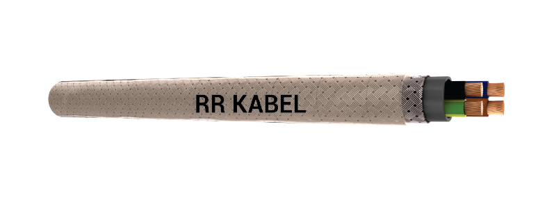
JB-YCY
- REACH
- RoHS
- CE


Application
For use as a data and control cable in machinery, computer systems etc. as well as a signal cable for electronics. The high level of screening ensures a high degree of interference protection. The dense screening assures disturbance-free transmission of all signals and impulses. The PVC-inner sheaths of these cables raise the mechanical strength. The applied clear transparent PVC outer sheath accentuates the optical view of the tinned copper braid. These cables are suitable for flexible use for medium mechanical stresses with free movements.
Standard
Adapted to DIN/BS EN 50525-2-51.
Technical Data
Nominal Voltage: Uo / U 300 / 500V up to 1.5 mm². Uo / U 450 / 750V for 2.5 mm² and above
Insulation Resistance: Min. 20 GΩ x cm
Temperature Range: Flexing -5°C to +70°C. Fixed installation -30°C to +70°C
Minimum Bending Radius: Flexing 20 x cable ø. Fixed installation 6 x cable ø
Test Voltage: 4000V
Breakdown Voltage: Min. 8000V
Mutual Capacitance (0.5 to 2.5 Sq. mm): core to core (approx.) – 150 nF/km
core to screen (approx.) – 270 nF/km
Cable Construction
Bare copper, fine wire conductors, EN 60228 Cl. 5.
Core insulation of TI2, EN 50363-3.
Core identification : As per VDE 0293-302/HD 308 S2 (Refer appendix table No. 1-1)
Green/yellow earth core in outer layer (3 cores and above).
Cores stranded in layers with optimal lay-length.
Special PVC inner jacket.
Tinned copper, braided screen, approx 85% coverage.
Transparent special PVC outer sheath.
Properties
PVC self-extinguishing and flame retardant according to EN 60332-1-2.
EMC: Electromagnetic compatibility
To optimise the EMC features we recommend a large round contact of the copper braiding on both ends.
Cable Design Parameters
| Part Number | No. of Cores and Nominal Cross Sectional Area (Sq. mm) |
Approx. Cable Diameter (mm) |
Approx. Copper Weight (kg/km) |
Approx. Cable Weight (kg/km) |
| 030601010216 | 2 x 0.5 | 7.9 | 37 | 124 |
| 030601020116 | 3G 0.5 | 8.3 | 44 | 139 |
| 030601030116 | 4G 0.5 | 8.8 | 53 | 168 |
| 030601040116 | 5G 0.5 | 9.6 | 60 | 205 |
|
|
|
|
|
|
| 030601060216 | 2 x 0.75 | 8.3 | 44 | 140 |
| 030601070116 | 3G 0.75 | 8.7 | 54 | 160 |
| 030601080116 | 4G 0.75 | 9.5 | 66 | 198 |
| 030601090116 | 5G 0.75 | 10.1 | 78 | 239 |
|
|
|
|
|
|
| 030601110216 | 2 x 1 | 8.6 | 53 | 156 |
| 030601120116 | 3G 1 | 9.2 | 65 | 182 |
| 030601130116 | 4G 1 | 9.8 | 79 | 221 |
| 030601140116 | 5G 1 | 10.7 | 94 | 272 |
|
|
|
|
|
|
| 030601160216 | 2 x 1.5 | 9.7 | 66 | 198 |
| 030601170116 | 3G 1.5 | 10.2 | 87 | 231 |
| 030601180116 | 4G 1.5 | 11.1 | 106 | 286 |
| 030601190116 | 5G 1.5 | 12.4 | 129 | 368 |
|
|
|
|
|
|
| 030601210216 | 2 x 2.5 | 11.2 | 95 | 271 |
| 030601220116 | 3G 2.5 | 11.8 | 126 | 318 |
| 030601230116 | 4G 2.5 | 13.1 | 159 | 412 |
| 030601240116 | 5G 2.5 | 14.3 | 193 | 511 |
|
|
|
|
|
|
| 030601260116 | 4G 4 | 13.4 | 264 | 565 |
|
|
|
|
|
|
| 030601280116 | 4G 6 | 15.6 | 365 | 732 |
| 030601290116 | 5G 6 | 17 | 442 | 909 |
| 030601300116 | 3G 10 | 17.8 | 453 | 889 |
|
|
|
|
|
|
| 030601320116 | 5G 10 | 21.6 | 711 | 1408 |
| 030601330116 | 3G 16 | 20.7 | 707 | 1274 |
| 030601340116 | 4G 16 | 22.6 | 917 | 1618 |
| 030601350116 | 5G 16 | 25.2 | 1128 | 2047 |
| 030601330116 | 3G 25 | 26.3 | 1064 | 1965 |
| 030601340116 | 4G 25 | 28.9 | 1386 | 2512 |
| 030601350116 | 5G 25 | 31.8 | 1708 | 3153 |
| 030601360116 | 3G 35 | 29.4 | 1453 | 2554 |
| 030601370116 | 4G 35 | 32.2 | 1900 | 3259 |
| 030601380116 | 5G 35 | 36.0 | 2347 | 4133 |
| 030601390116 | 3G 50 | 35.1 | 2048 | 3653 |
| 030601380116 | 4G 50 | 38.8 | 2688 | 4701 |
| 030601390116 | 4G 70 | 43.7 | 3732 | 6229 |
| 030601400116 | 4G 95 | 50.4 | 4915 | 8123 |
| 030601410116 | 4G 120 | 56.8 | 6198 | 10118 |
| 030601420116 | 4G 150 | 62.2 | 7600 | 12511 |
| 030601430116 | 4G 185 | 67.8 | 9334 | 15306 |
Note:
- *JB = With green/yellow earth core
- OB = Without green/yellow earth core
- For current ratings to DIN VDE 0298-4 refer table no. 12-3 of Appendix.
